How to become a good drone structural designer
- aerialdynamictech
- Sep 22, 2025
- 28 min read
Job Positioning and Core Values: From “Drawer” to “System Balancer”
In the UAV R&D system, structural design is the core hub connecting "design concept" and "project implementation" - it must not only carry the flow field requirements of aerodynamic design, but also meet the installation constraints of flight control, power, load and other systems. It also needs to find the optimal solution among weight, strength, cost, and lifespan. Different from the simplified design of consumer-grade drones, the structural design of industrial-grade (especially military and long-endurance civilian) drones directly determines the mission capabilities and safety boundaries of the entire aircraft. Its job value needs to be deeply deconstructed from the three dimensions of "application scenario differences", "full-cycle R&D intervention" and "multi-objective balance".
Application scenarios determine the core orientation of structural design. The application scenarios of UAVs have expanded from early military reconnaissance to civilian surveying and mapping, logistics and transportation, forest fire prevention, ocean monitoring and other fields. Different scenarios have completely different priority requirements for structural design. This is the primary cognitive basis for excellent structural designers: Military reconnaissance/strike UAVs: The core requirement is "high survivability + high load capacity." Civilian long-endurance surveying and mapping drones: The core requirement is "lightweight + low maintenance cost". Logistics and transportation drones: The core requirement is "large payload + easy maintenance".

Core Responsibilities and Nodes of Structural Designers in the Full R&D Cycle The R&D cycle of a drone is usually 9 to 18 months. Structural designers need to be involved in the entire process and lead key decisions. The focus of responsibilities at different stages is significantly different. The specific nodes and outputs are shown in the table below:


The value of "multi-objective balance" of structural designers: systems thinking that transcends technology. Excellent structural designers are by no means "engineers who only look at drawings", but are "balancers" of the performance of the entire machine - they need to find the optimal solution between conflicting goals. This balancing ability directly determines the engineering value of the design.
The balance between lightweight and strength: quantitative design and iterative optimization. The core goal of lightweighting is to "minimize structural weight while meeting strength requirements", but it is necessary to avoid falling into the misunderstanding of "lighter weight is better" (excessive weight reduction may lead to insufficient strength or soaring process costs). In practice, a balance needs to be achieved through "quantitative indicators + iterative optimization". To define quantitative indicators, first clarify the reasonable range of the weight coefficient (structural weight/complete aircraft weight) (25% to 30% for military UAVs, 30% to 35% for civilian use), and at the same time determine the strength safety margin (≥1.5 under flight load, ≥1.2 under ground load) according to GJB/GB standards.
For example, the total weight of a military UAV is 1500kg, the structural weight needs to be controlled within 450kg, and the safety margin of the wing under the maximum aerodynamic load must be ≥1.5. The iterative optimization method adopts the three-step method of "topology optimization, size optimization, and process optimization". Taking the design of the wing main beam as an example, in the first step, through ANSYS topology optimization, under given loads and boundary conditions, the optimal material distribution of the main beam is obtained (such as a variable cross-section form that is thin in the middle and thick at both ends);The second step is to optimize the size of the topology results and determine the web thickness, flange width and other parameters to ensure that the stress meets the requirements; the third step is to combine the process feasibility and change the optimized complex section into an "I-shape" (for ease of machining). The final weight is reduced by 12%, and the strength safety margin is maintained at 1.6.

The balance between performance and cost: life cycle cost thinking. The cost of structural design not only includes manufacturing costs, but also maintenance costs and life costs. For example, the initial design of an unmanned transport aircraft used a full carbon fiber fuselage, but it was subsequently discovered that the carbon fiber repair cost was high and the lifespan was only 500 flight hours;The structural team changed to an "aluminum alloy frame + aluminum alloy sheet metal skin" structure, which greatly reduced the repair cost, extended the life to 1,500 flight hours, and reduced the whole life cycle cost by 60%.Key decision-making method: Build a "cost-performance matrix" to quantitatively score the manufacturing costs (materials, processing, assembly), maintenance costs (maintenance cycle, repair difficulty), and life costs (replacement frequency) of different design solutions, and finally select the solution with the highest comprehensive score.
Balancing aerodynamic compatibility and structural functionality: interdisciplinary collaborative design. Aerodynamic design pursues "smooth curved surfaces and low resistance", while structural design requires the arrangement of functional components such as reinforcing ribs and mounting brackets. The two are prone to conflicts. The solution strategy is “early collaboration + integrated design”. Early collaboration: In the planning stage, structural designers and aerodynamic designers jointly participate in "configuration coordination" to clarify the "unchangeable areas" and "adjustable areas" of the aerodynamic shape.
For example, the aerodynamic designer of a long-endurance UAV proposed that the maximum thickness of the airfoil should be at 30% of the chord length. The structural designer needs to arrange the main beam here. After consultation, the thickness of the main beam web is reduced from 5mm to 3mm to ensure that the airfoil thickness deviation is ≤2% (meeting aerodynamic requirements). Integrated design: The "composite integrated molding" technology is used to integrate structural reinforcement with aerodynamic shape. For example, the wing of a long-endurance drone adopts "integrated skin with built-in stiffeners" and is molded in one step through the molding process. This not only ensures the smoothness of the aerodynamic surface, but also eliminates the traditional skin and stiffener connection process.
Balancing short-term test flight and long-term life: Fatigue design front-end. Some designers only focus on “passing test flight verification” and ignore long-term fatigue damage, which may lead to structural failure of the UAV in the middle of service. "Fatigue life" needs to be advanced to the detailed design stage to compile the fatigue load spectrum and optimize the detailed design. The fatigue load spectrum compilation formula compiles a typical fatigue load spectrum (for example, the cruise phase accounts for 60% and the maneuvering phase accounts for 20%) based on the mission profile of the UAV (takeoff → climb → cruise → landing), and calculates the fatigue life according to the Miner linear cumulative damage theory (needs to meet 1.2 times the redundancy of the design life); detail design optimization is to optimize fatigue-sensitive parts (such as bolt holes, welds, chamfers).
Professional competency requirements: Build a competency system of “theory + tools + practice + interdisciplinary”
UAV structural design is a field that strongly combines "theoretical depth" and "engineering practice." Excellent designers need to have a "pyramid" capability structure. The bottom layer is a solid theoretical foundation, the middle layer is skilled tool application, the upper layer is engineering intuition and interdisciplinary collaboration capabilities, and the top layer is continuous learning and innovation capabilities. The following is expanded from four dimensions, combined with specific technical scenarios and cases, to analyze the practical requirements of each capability.

Theoretical basis: from "formula memory" to "engineering application"
Theoretical knowledge is not an "examination point", but the "underlying logic" for solving engineering problems. UAV structural design needs to focus on mastering four major theoretical systems and being able to translate them into design decisions.
Aircraft structural mechanics: core theory of thin-walled structures and load transfer. Most aircraft structures are "thin-walled structures" (such as skins and webs). It is necessary to master the stress characteristics and calculation methods of thin-walled structures to avoid design errors caused by theoretical misunderstandings. With the application of beam theory, the wing can be simplified as a "thin-walled beam", and its bending strength and torsional strength need to be calculated. According to thin-wall torsion theory, the fuselage will twist when subjected to horizontal loads, and the shear strength of the skin needs to be checked. Common misunderstanding warning: Some designers equate "thin-walled structure" with "weak structure", and excessively increasing the thickness leads to weight overrun. In fact, thin-walled structures can achieve high stiffness through "section optimization" (such as I-shaped, box-shaped).


Mechanics of Materials: Accurate judgment of material properties and failure mechanisms. The essence of structural design is to "select appropriate materials and use their properties to achieve design goals." It requires an in-depth understanding of the mechanical properties, environmental adaptability and failure mechanisms of materials. Performance comparison and selection of commonly used materials. Commonly used materials for drones include aluminum alloys, titanium alloys, and composite materials. They need to be selected according to the function of the components (the following table shows a comparison of key performance parameters).
For example, the temperature in the engine compartment of a drone can reach up to 150°C. The strength of aluminum alloy 7075-T6 will drop by 30% above 120°C, so Ti-6Al-4V titanium alloy is used to make the engine bracket. The wings need to be lightweight, so T700 carbon fiber composite material is used, and aramid fibers are pasted on the wing tips that are susceptible to impact (impact strength is 3 times that of carbon fiber). The identification of material failure mechanisms requires the ability to determine the cause based on the failure phenomenon to avoid repeated design errors.
For example, the skin of a UAV wing appeared "stratified". Analysis showed that there were bubbles (porosity >5%) during the lamination of the composite material, and the curing temperature was insufficient (set at 120°C, but actually only 110°C), resulting in a decrease in interface bonding strength. The rectification measures included: optimizing the layup process (increasing the pre-pressure step), strictly monitoring the curing temperature (error ±2°C), and controlling the final porosity within 2%.

Fundamentals of Aerodynamics: Understand the origin and distribution of aerodynamic loads. Structural design needs to carry aerodynamic loads. Failure to understand aerodynamic principles may lead to incorrect load calculations. Three core skills need to be mastered. First, master the calculation method of aerodynamic load; second, master the distribution law of aerodynamic load. The aerodynamic load of the wing is not uniformly distributed, but "large at the wing root and small at the wing tip" (approximately triangular distribution). Therefore, the cross-sectional size of the main beam needs to gradually decrease from the wing root to the wing tip;Third, understand the relationship between flutter and structural stiffness. Flutter is a harmful vibration of the wing during high-speed flight, which may cause structural damage and needs to be avoided through "stiffness design". For example, after the flight speed of a UAV increases, signs of wing flutter appear. By increasing the thickness of the wing skin and adding wing ribs, the bending stiffness and torsional stiffness of the wing are improved, and finally the flutter critical speed is increased to meet the design requirements.
Aeronautical structural design specifications: ensuring design compliance and safety. Standards are "the summary of previous experience" and must be strictly followed to avoid breaking the safety bottom line due to "innovation". The core specifications that UAVs need to follow include: GJB 2749A-2016 "Military Aircraft Structural Strength Specification" applicable to military UAVs (stipulating the design load, safety margin, and test methods of structural strength).GJB 150A-2009 "Environmental Test Method for Military Equipment Laboratory" (specifies environmental test requirements for salt spray, high and low temperature, vibration, etc.), GB/T30045-2013 "General Requirements for Unmanned Aerial Vehicle Systems" (which specifies structural strength, reliability, maintainability requirements) and ISO 21378-2021 "Safety Requirements for Design and Operation of Unmanned Aerial Vehicle Systems" (focusing on risk control of structural failure) applicable to civilian UAVs.
Engineering tools and software capabilities: from “knowing how to use” to “using them well”
Tools are the "amplifiers" of design efficiency. Excellent designers must not only be proficient in operating software, but also be able to improve design accuracy and efficiency through "parameterization and automation" to avoid "duplication of work" and "human errors".
3D modeling software: Parametric and collaborative design of CATIA/UG. Three-dimensional modeling is not about "drawing a look", but "building a driveable and iterable digital model", which requires mastering parametric design and collaborative design skills. Parametric modeling techniques, taking CATIA as an example, when building a wing model, key parameters such as wingspan, chord length, sweep angle, and relative thickness need to be set as "design parameters". During subsequent modifications, you only need to adjust the parameters and the model will automatically update. Interference inspection and collaborative design. Multi-professional teams (aerodynamics, flight control, power) work in the same digital model and need to conduct interference inspection in real time. Through CATIA's "DMU spatial analysis" function, existing interference can be discovered and adjusted in a timely manner to avoid subsequent assembly problems.
Finite element analysis software: Engineering applications of ANSYS/NASTRAN. Finite element analysis is not a "show off skills" but a "tool to verify designs and discover risks." It is necessary to master the entire process from modeling to result interpretation to avoid "disconnection between analysis and reality." The whole process of static analysis (taking ANSYS Workbench as an example), first, perform geometric cleaning, and after importing the CATIA model, delete irrelevant features (such as chamfers and threads, which can be simplified later) to avoid difficulties in meshing. Second, meshing is performed, using hexahedral mesh (unit type SOLID186) for key parts (such as the wing root), and tetrahedral mesh (unit type SOLID187) for non-critical parts (such as skin edges); third, material assignment, assigning material properties to different parts (such as wing mask) For T700 carbon fiber, orthotropic properties need to be defined: E1=230GPa, E2=10GPa, G12=5GPa); fourth, apply loads and constraints. According to the aerodynamic load report, apply distributed loads on the upper surface of the wing, and apply "fixed constraints" at the connection between the fuselage and the wing.Fifth, analyze the solution and results. After running the solution, check the stress cloud diagram and displacement cloud diagram. If the maximum stress exceeds the material yield strength, the design needs to be optimized (such as adding reinforcing plates). To check modal analysis and vibration, use the ANSYS Modal module to solve for the first six natural frequencies to avoid the risk of resonance. Fatigue analysis application uses the ANSYS nCode DesignLife module to import the fatigue load spectrum and calculate the structural fatigue life. Engineering interpretation of analysis results avoids "numerical theory only" and needs to be combined with engineering experience to judge the rationality of the results.

PDM/PLM system: digital design and data management. The PDM (Product Data Management)/PLM (Product Lifecycle Management) system is "the core of collaborative design and data traceability" and requires mastery of data management and process control. Data management skills, in Siemens Teamcenter (PLM system), three-dimensional models, engineering drawings, analysis reports, and process documents need to be associated with "part numbers" to ensure data consistency. Process control and version management, design changes must go through the "change process" (application → review → approval → release) to avoid arbitrary modifications.
Auxiliary tools: Excel/Python automated calculations. Auxiliary tools can greatly improve design efficiency and avoid "manual calculation errors". You need to master Excel formulas and Python scripting.
Engineering intuition and comprehensive judgment: from “experience accumulation” to “risk prediction”
Engineering intuition is not "metaphysics", but "quick decision-making ability formed after extensive engineering practice", which can help designers quickly find key contradictions in complex problems and avoid "over-analysis" or "risk of omission". The following analyzes the cultivation methods and application scenarios of engineering intuition: intuitive judgment of weight and strength balance. Excellent designers can quickly determine whether weight and strength are balanced through "component size, material type, and load size" to avoid "blind calculations." Intuitive cultivation method to accumulate "weight-strength" data of different models of drones.
Quick identification of risky parts of working conditions. Under different working conditions (takeoff, climb, cruise, maneuver, recovery), the structural risk areas of UAVs are different, and excellent designers can quickly identify them. Risk locations and reasons for each operating condition: takeoff/landing, landing gear (withstands ground impact load), wing root (large bending moment when taking off and raising the head); cruise, fuselage (withstands axial load generated by aerodynamic drag), tail (withstands horizontal stabilizer load) ; Maneuvering, the wing (withstands overload load, such as the load doubles during 2g maneuvers), the connection between the fuselage and the wing (load transfer is concentrated); recovery (parachute/taxiing), the bottom of the fuselage (withstands landing impact), the parachute connection point (withstands tension).
Quick troubleshooting of design errors. In the face of structural failure (such as cracks and deformation), excellent designers can quickly locate the cause through "failure phenomena" and avoid "blind testing".
Interdisciplinary communication and learning capabilities: from "professional barriers" to "collaboration and win-win"
Structural design requires collaboration with aerodynamics, flight control, power and other disciplines. Excellent designers need to be able to "understand non-professional language and translate it into structural design constraints" and actively learn interdisciplinary knowledge to avoid "design disconnection".
Communication with aerodynamic designers: Balancing form and structure. Aerodynamic designers focus on "low resistance, high lift", structural designers focus on "easy manufacturing, high strength", and the core of communication is "finding the compatibility point between shape and structure".
Communicate with avionics designers and engineers: reserve space for installation and maintenance. The avionics system includes sensors (IMU, GPS, steering gear), cables, and data links. The structural design must reserve sufficient installation space and maintenance access. Obtain the "three-dimensional model and installation requirements" of the avionics equipment, design the "modular installation bracket", and reserve access hatches to facilitate debugging and maintenance.
Communication with power&system designers and engineers: balance between load-bearing and heat dissipation. The power system (engine, fuel tank, pipeline) needs structural support, and heat dissipation and fuel sloshing need to be considered. The core of communication is "safe load + functional guarantee". Obtain the "load and temperature requirements" of the power system, design the "shock absorption and heat insulation structure", and optimize the fuel tank layout.

Design principles and ways of thinking: from "technical specifications" to "engineering philosophy"
UAV structural design is not a "mechanical application of formulas", but an engineering practice of "pursuing the optimal solution under constraints". It needs to follow five core principles. These principles are not only technical specifications, but also the "engineering philosophy" of excellent designers, which need to be internalized in every step of design decision-making. The following combines specific cases to analyze the connotation and practical methods of each principle to avoid "disconnection between principles and practice".
Dynamic balance between lightweight and strength: optimal solution under quantitative constraints
Lightweight is the eternal theme of UAV structural design, but "lightweight" must be based on "meeting strength requirements". The two are not an "either-or" contradiction, but a unity of "dynamic balance". Excellent designers need to master the "quantitative balancing method" to avoid "blind weight loss" or "over-conservatism".
Lightweight quantitative goals and boundaries. Lightweighting is not "the lighter the better", but "minimizing the weight when all constraints are met". Three quantitative boundaries need to be clarified: first, strength constraints. According to the GJB/GB standard, the safety margin of the structure under the design load must be met, flight load ≥ 1.5, ground load ≥ 1.2, fatigue life ≥ 1.2 times the design life.Second, stiffness constraints, the structural stiffness needs to meet aerodynamic and flight control requirements to avoid aerodynamic shape distortion, and the torsional stiffness of the tail must meet the flight control surface control requirements. Third, due to process constraints, lightweight design must consider process feasibility. For example, the thickness of the composite skin cannot be less than 0.8mm (less than this thickness will easily lead to molding defects), and the bolt hole diameter cannot be less than M3 (less than this specification, it will easily slip).
Practical methods of dynamic balancing: iterative optimization and comparison of multiple alternatives. Dynamic balance is not a "one-time design in place", but a process of "multiple rounds of iteration and continuous optimization". Two core methods need to be mastered, namely the zone optimization method and the multi-solution comparison method. The iterative process of the iterative optimization method includes initial design, strength verification, first optimization, re-verification, second optimization, and final verification. The multi-solution comparison rule is to design multiple lightweight solutions for the same component, and select the optimal solution based on four-dimensional scoring of "weight, strength, cost, and craftsmanship.
"Common Misunderstandings and Avoidance Strategies. Over-reliance on composite materials to reduce weight, mistakenly believing that "composite materials = lightweight", and ignoring its cost and process difficulty. For example, the initial design of an unmanned transport aircraft used a full carbon fiber fuselage, but later discovered the maintenance cost and changed it to an aluminum alloy fuselage, which has lower life cycle costs. Ignore the details of weight reduction, only focus on the main beam, fuselage and other large components, and ignore the weight reduction of small components. For example, the total weight of a drone's bolts reaches 2kg. By changing some M8 bolts to M6 high-strength nuts and using titanium alloy nuts, the cumulative weight reduction effect is significant. By establishing a "lightweight list of all parts" to avoid misunderstandings, from large parts (wings, fuselage) to small parts (bolts, nuts, brackets), the space for weight reduction is checked one by one; at the same time, the "cost-to-weight ratio" indicator (yuan/kg) is used to give priority to solutions with low cost and good weight reduction effect.

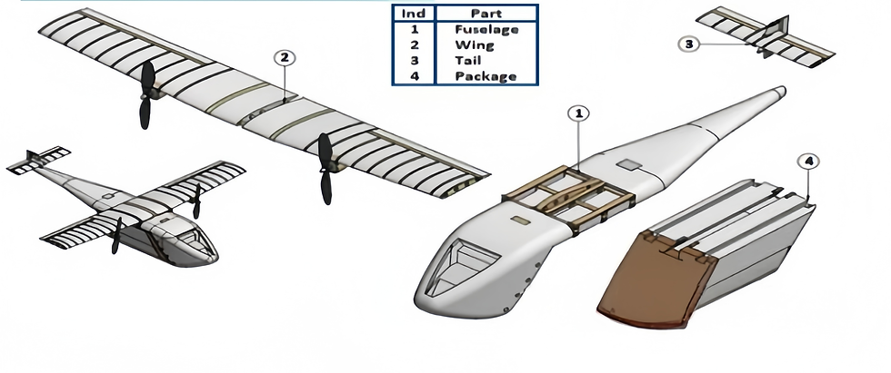
Modularity and ease of maintenance: Design for the full life cycle
The full life cycle of a drone includes "design, manufacturing, use, maintenance, and scrapping." The structural design needs to take into account "manufacturing efficiency" and "maintenance convenience." Modular design is the core method to achieve this goal. By splitting the structure into independent modules, "quick assembly, quick repair, and quick modification" can be achieved.
Core principles of modular design. Modular design is not "simple splitting", but "dividing modules according to functions and maintenance requirements", and needs to follow three major principles: first, the principle of functional independence, each module implements a single function, such as mission load module, power module, avionics module, and the modules are connected through standardized interfaces without interfering with each other; second, the principle of interface standardization, the connection interfaces (mechanical interfaces, electrical interfaces) between modules need to be standardized, and modules with the same function of different models are interchangeable.Third, the principle of maintenance accessibility means that the installation position of modules needs to be convenient for maintenance. For example, vulnerable parts (servos, sensors) modules should be arranged on the side or top of the fuselage and can be accessed through removable covers. Heavy-duty modules (engines, fuel tanks) should be arranged in the middle of the fuselage to facilitate hoisting and replacement.
Practical examples of modular design. Taking an unmanned transport aircraft as an example, the entire module is divided into six major modules: wing module, fuselage module, tail module, power module, mission load (cargo) module, and landing gear module. Among them, the most important wing module adopts a "three-section" design (left outer wing, right outer wing, center wing), which is connected through quick-release bolts. The center wing and the fuselage are connected through "positioning pins + bolts". The positioning accuracy ensures that the aerodynamic shape of the wing is consistent after installation.The benefits of modular design include improved manufacturing efficiency, maintenance efficiency and modification flexibility. Each module can be manufactured in parallel (wing modules and fuselage modules are produced at the same time), compressing the overall manufacturing cycle and facilitating decomposition, maintenance and modification.
Key details designed for ease of maintenance. The easy maintenance design needs to pay attention to three details: "inspection space, tool accessibility, and fault diagnosis" to avoid "neglect during design and difficulty in maintenance." In the design of the inspection space, the size of the access cover must be larger than the size of the maintenance tools and components. For example, the size of the servo access cover must be ≥ the size of the servo + 50 mm (to facilitate hand insertion), and a wrench space must be reserved for the bolt connection part (for example, a wrench space of ≥ 20 mm must be reserved for M10 bolts).Tool accessibility design, commonly used maintenance tools (such as wrenches, screwdrivers) must be able to easily reach maintenance parts to avoid "visible but intangible". Fault diagnosis design, arrange sensors (strain gauges, temperature sensors) on key components (such as landing gear, main beam) to monitor the structural status in real time and automatically alarm in case of failure.
Redundancy and Safety: Design Thinking for Uncertainty
UAVs may face uncertain risks such as "unexpected loads" (such as sudden winds, bird strikes) and "component failures" (such as loose bolts and skin cracks) during flight. The structural design needs to improve safety through "redundant design" and set up backups or reserve safety margins in key parts to ensure that "a single failure does not cause the entire aircraft to fail."
According to the type of risk, redundant design is divided into three categories: "structural redundancy", "load redundancy" and "functional redundancy". Structural redundancy is to set up backup structures in key load-bearing components. For example, the main beam of the wing adopts a "double beam structure" (main beam + auxiliary beam). The main beam bears 70% of the load and the auxiliary beam bears 30%. If the main beam cracks due to fatigue, the auxiliary beam can temporarily bear 50% of the load to ensure the safe return of the drone.The wing of a military UAV adopts a double-beam structure. During the test flight, cracks appeared in the main beam (length 20mm). However, the auxiliary beams worked normally and the UAV was successfully recovered. Load redundancy refers to the "unexpected load redundancy" reserved when designing loads. For example, the normal flight load is 1.0g, and the strength is calculated based on the 1.5g load during design to cope with unexpected situations such as gusts and maneuvers.Functional redundancy is the backup of key functional components. For example, the landing gear buffer system uses a "double air chamber buffer". If one air chamber fails, the other air chamber can provide 70% of the buffering capacity to avoid excessive impact during landing.
Redundant design is not "the more the better". It is necessary to avoid "excessive redundancy leading to weight overruns" and to follow the principle of "prioritize key parts and control costs". Key parts are identified based on the "fault impact degree". Parts that affect flight safety after a failure (such as main beams, landing gear, and fuselage frames) need to be designed redundantly; parts that do not affect safety after a failure (such as skin edges, non-load-bearing brackets) can be simplified in design.
It is necessary to establish a "redundant design list" to clarify key parts, redundancy types, and verification methods. After redundant design, it must be tested and verified to ensure that the redundant function is effective.
Craftsmanship and cost control: from “able to design” to “able to manufacture”
An excellent design must not only be able to fly, but also be able to be built, repaired, and low-cost. Craftsmanship and cost control are the keys to design implementation. If craftsmanship is ignored, no matter how good the design is, it cannot be mass-produced; if cost is ignored, the design can only stay in the laboratory.
The core requirements of craftsmanship design. Process design needs to be "manufacturing-oriented and assembly-oriented" and needs to master the characteristics and design requirements of different processes. Machining technology requires that the shape of the part be as simple as possible and avoid complex curved surfaces (such as deep cavities and narrow slits). If complex curved surfaces are required, they can be split into multiple simple parts; dimensional tolerances and geometric tolerances must meet the processing capabilities.For example, the dimensional tolerance of ordinary machining can reach IT10, and precision machining can reach IT7 to avoid "hyper-precision" design; the wall thickness of parts is uniform to avoid "violent transition between thick and thin walls" that will cause stress concentration and deformation during processing. The molding process of composite materials requires that the ply design consider the molding feasibility. For example, the ply angle should include 0°, 45°, -45°, and 90°, and avoid a single angle.The curvature radius of the parts cannot be too small. For example, for molded composite parts, the inner fillet should be ≥3mm and the outer fillet should be ≥2mm to avoid fiber wrinkles during molding.The size of the parts cannot exceed the size of the mold, and space for mold installation must be reserved. The assembly process requires a reasonable fit between parts and a reasonable assembly sequence, with internal parts installed first and then external parts, heavy parts first and then light parts; space for assembly tools is reserved, such as wrench space for bolted connections.
Core methods of cost control. Cost control needs to run through the entire design process, from the "plan stage" to the "detailed design stage", and gradually refine the cost targets. In the planning stage, cost estimation and target setting are done well. Refer to the cost structure of similar drones (for example, the structural cost accounts for 30% to 40% of the whole machine cost) and use the "analogy method" to estimate the cost and set the cost target.Allocate costs by components, for example, the wing cost accounts for 30% of the structural cost, the fuselage accounts for 25%, the landing gear accounts for 20%, the tail accounts for 15%, and others account for 10% to ensure that the cost of each component is controllable.Cost optimization measures in the detailed design stage include optimizing material costs, prioritizing cost-effective materials, optimizing processing costs, reducing the number of parts, simplifying part shapes, etc. Full life cycle cost control not only focuses on manufacturing costs, but also considers maintenance costs and scrap costs.
Design for test flight and full life cycle: from "one-time verification" to "long-term reliability"
Excellent structural design must not only pass "test flight verification", but also ensure that the UAV continues to be reliable throughout its life cycle. Test flight risks, environmental impact and fatigue accumulation must be considered in advance to avoid the problem of "passed test flight but failed in service".
Structural design for test flight: risk prediction and test adaptation. Test flight is a key link to verify the structural design, but there are risks such as "sudden loads" and "unknown working conditions" during the test flight. The structural design must be "test-friendly" and "emergency safety". Based on test flight subjects (such as low-speed taxiing, high-speed taxiing, first flight, maneuvering test flight), flight test risk prediction and structural strengthening are carried out.For example, before the first flight, it is necessary to focus on strengthening the "connection between the landing gear and the fuselage" (to withstand the ground impact load) and the "wing root" (to withstand the take-off nose-up bending moment).The test sensor layout is designed and sensor installation interfaces are reserved at key locations to facilitate real-time monitoring of structural stress and deformation. Emergency safety design, set up "emergency damage points" to prioritize damage to non-critical components under extreme loads and protect the core structure.
Environmentally adaptable design: resist erosion in multiple scenarios. The service environment of UAVs is complex, and they need to deal with environments such as high temperature, low temperature, humidity, salt spray, sand and dust. The structural design needs to resist environmental erosion through "material selection", "surface treatment" and "sealing design".
Full life cycle fatigue management: from "passive maintenance" to "active early warning". Fatigue damage is the main cause of mid-service failure of UAVs (accounting for about 60% of structural failures), and full life cycle management needs to be achieved through "fatigue design" and "health monitoring". Based on Miner's linear cumulative damage theory, a "full life cycle fatigue load spectrum" (including the number of load cycles in typical working conditions such as takeoff, cruise, maneuvering, and landing) was compiled, and structural details were optimized accordingly. Based on the fatigue life of the structure, a "graded maintenance plan" is developed.

Daily work and growth path: from "execution level" to "decision-making level"
The growth of a UAV structural designer is a cyclical process of "theory-practice-review". It is necessary to accumulate experience and improve capabilities in daily work, and gradually grow from a junior engineer who "completes component design" to a senior engineer who "leads the entire aircraft structure plan". The following is an analysis of the work focus and growth methods at each stage based on specific work scenarios.
Plan phase: from "requirements interpretation" to "configuration output"
The plan stage is the "top-level planning" of structural design. The core is to convert "task requirements" into "structural configuration plans". It is necessary to quickly output feasible plans and coordinate across professional boundaries. First, mission requirements are dismantled and quantified, and fuzzy mission requirements (such as "long endurance, large load") are converted into specific design indicators; second, structural configuration scheme design, the configuration (such as mid-monoplane wing, high monoplane wing, swept wing) is selected according to the mission requirements, and a preliminary check of weight budget and strength is carried out; third, cross-professional boundary coordination is carried out, and the design boundaries are determined in consultation with aerodynamics, avionics, and power professionals.
Preliminary design stage: from "configuration plan" to "parametric model"
The preliminary design stage requires converting the "conceptual configuration" in the program stage into an "analyzable parametric model", verifying the strength of key components through finite element analysis, and determining material and process plans. First, parametric modeling of the entire aircraft, using CATIA/UG to establish a three-dimensional parametric model of the entire aircraft. Key parameters (such as wingspan, chord length, main beam cross-section size) can be driven to be modified; second, finite element analysis of key components, focusing on the statics, modal and fatigue performance of key components such as main beams, fuselage frames, and landing gears; third, material and process plans are determined, and materials and processes are selected based on the analysis results and cost targets.
Detailed design stage: from "model analysis" to "project implementation"
The detailed design stage is the key to "converting design into product". It is necessary to output manufacturable engineering drawings and process documents, solve processing and assembly problems, and ensure that the design is "implementable and mass-produced." First, output engineering drawings according to GB/T 1800.1-2022 "Product Geometric Technical Specifications Limits and Cooperation No. 1" Part: Basis of Tolerances, Deviations and Fits" Output engineering drawings, including dimensional tolerances, geometric tolerances, material markings, surface roughness, heat treatment requirements, etc.; second, prepare manufacturing process documents, prepare part processing process cards, assembly process cards, inspection process cards; third, solve process review and problems, conduct process review with process, manufacturing, and inspection teams to solve processing and assembly problems.
Testing and improvement phase: from “theoretical verification” to “design optimization”
The test and improvement stage is a closed loop of "verifying the design, discovering problems, and optimizing the design". It requires leading structural tests, analyzing flight test data, proposing optimization plans and verifying them. First, the design and implementation of structural test plans, design static test, vibration test, and fatigue test plans, and organize their implementation; second, test flight data collection and analysis; third, design optimization and verification, propose and verify optimization plans for problems discovered during tests and test flights.
Growth path: Capability transition from “junior” to “advanced”
The growth of UAV structural designers needs to go through three stages: "beginner→intermediate→advanced". The ability requirements and growth methods of each stage are different, and clear goals and plans are required.
Primary stage (1~3 years): lay a solid foundation and master the tools and processes.
Core competency requirements: Master the basics of aircraft structural mechanics and material mechanics, and be able to complete the strength estimation of simple components (such as tails, landing gear brackets); be proficient in using CATIA/UG to build three-dimensional models of parts, and be able to output engineering drawings of simple parts; master the basic operations of ANSYS, and be able to complete static analysis of simple components (such as brackets);Understand the research and development process and can assist in completing the weight budget in the planning stage and model modification in the preliminary design stage. Growth method: Participate in projects, starting from "component-level design", such as being responsible for tail skin design, landing gear bolt selection, and accumulate practical experience; learn specifications, systematically study GJB/GB standards (such as GJB 2749A-2016, GB/T 30045-2013), and master the compliance requirements of structural design; be taught by a master and learn from intermediate/senior designers.For example, learn modeling skills of finite element analysis and drawing annotation specifications; skill certification, obtain CATIA/UG advanced certification, ANSYS analysis certification, and improve tool application capabilities.
Intermediate stage (3~8 years): Leading the design and possessing optimization and coordination capabilities.
Core competency requirements: Ability to independently complete the structural design of the entire aircraft, and prepare weight budget and strength verification reports; Ability to lead finite element analysis (statics, modal, fatigue) of key components (such as wings, fuselage), and propose optimization plans; Ability to prepare a full set of engineering drawings and process documents to solve processing and assembly problems; Have the ability to coordinate across disciplines, and be able to negotiate design boundaries with aerodynamics, avionics, and power teams to promote problem solving.Growth method: Leading projects, responsible for the whole structure design of small and medium-sized UAVs, and independently completing the entire process from plan to test; technical research, conducting technical research on complex problems (such as composite material delamination, structural fatigue failure) to form solutions; cross-professional learning, learning basic knowledge of aerodynamics and flight control (such as aerodynamic load calculation, flight control sensor installation requirements) to improve collaboration capabilities; summarizing experience, writing technical documents (such as "Composite Skin Design Guide" and "Finite Element Analysis Modeling Specifications") to accumulate experience.
Advanced stage (more than 8 years): Control the overall situation and become a technical decision-maker.
Core competency requirements: Have the ability to control the entire life cycle, and be able to optimize structural solutions from the entire process of design, manufacturing, maintenance, and scrap; be able to lead the overall structural design of large/complex UAVs (such as military surveillance and attack integrated UAVs, large unmanned transport aircraft) and determine the technical route; have the ability to coordinate cross-professional resources, promote multi-professional collaboration such as aerodynamics, avionics, power, technology, etc., to solve major technical bottlenecks; be technologically forward-looking, and be able to track new materials and new technologies (such as 3D printing, digital twins), and apply them to structural design.Growth methods: Leading major projects, responsible for the overall structural design of large-scale UAV models, formulating technical solutions and risk control strategies; technological innovation, promoting the application of new technologies (such as using metal 3D printing for engine bracket design), and improving product competitiveness; team building, leading the team to carry out technical research, training junior/intermediate designers, and establishing a structural design team capability system; industry exchanges, participating in international/domestic UAV technology conferences, and tracking the forefront of the industry.
Teamwork and soft power: from “technical craftsmen” to “collaborative hubs”
UAV research and development is a systematic project of "multi-professional collaboration". Structural design, as a "hub connecting various professions", requires not only solid technical capabilities, but also excellent collaboration and soft power to avoid the problem of "excellent technology but inefficient collaboration".
Cross-professional collaboration: clear interfaces and efficient collaboration
Structural design requires collaboration with aerodynamics, flight control, power, mission load, technology, flight test and other disciplines. The core is "clear interfaces, establishment of rules, and efficient communication."
Cooperate with pneumatic professionals to ensure that the shape and structure are compatible. The aerodynamic shape meets the structural load-bearing and manufacturing requirements, and the structural design does not affect aerodynamic efficiency. At the plan stage, aerodynamic professionals output "aerodynamic shape digital models" (such as airfoils and fuselage sections). Structural designers evaluate the structural feasibility of the shape (such as whether the main beams can be arranged and whether the skin can be formed), and feedback modification suggestions (such as changing the sharp corners of the fuselage to rounded corners to facilitate composite material molding).In the preliminary design stage, the aerodynamics professional outputs an "aerodynamic load report" (such as wing lift distribution, fuselage resistance), and the structural designer conducts strength analysis accordingly; in the detailed design stage, the structural designer outputs a "structural appearance digital model" (including skin thickness, stiffener arrangement), and the aerodynamic team carries out "structural appearance aerodynamic analysis". If the aerodynamic resistance increases by more than 5%, structural details need to be optimized (such as changing external stiffeners to built-in).
Cooperate with avionics professionals to ensure equipment installation space is suitable. Reserve installation space and maintenance access for the avionics system (sensors, servos, cables) to ensure normal flight control functions. In the planning stage, the "avionics component list" (including the size, weight, and installation requirements of IMU, GPS, and servos) is output, and the structural designer reserves installation space in the fuselage configuration; in the preliminary design stage, the structural team outputs the "digital model of the internal layout of the fuselage," and the avionics professional checks the component installation space and cable direction, and negotiates and adjusts the layout if there is interference; in the detailed design stage, the structural designer designs the "avionics equipment installation bracket."
Cooperate with power professionals to balance load-bearing and heat dissipation. Provide reliable support for the power system (engine, fuel tank, pipeline), while meeting heat dissipation and fuel storage requirements. In the planning stage, the power professional outputs "power system parameters" (such as engine power, weight, operating temperature, fuel tank capacity, weight), and the structural designer designs the layout of the engine room and fuel tank (such as reserved heat dissipation space in the engine room, and the fuel tank is arranged in the middle and rear of the fuselage, close to the center of gravity).In the preliminary design stage, the structural team carried out "engine bracket strength analysis" (withstanding engine weight and vibration load); in the detailed design stage, the structural designer designed the "engine compartment heat dissipation structure" (such as opening heat dissipation holes and installing cooling fans), and the power professional carried out "heat dissipation testing" and iterated based on the test results.
Collaboration between process/production professionals completes the connection between design and manufacturing, ensuring that the design can be processed, assembled, and mass-produced, and reduces manufacturing costs and cycles. In the preliminary design stage, the process conducts a "DFM (Design for Manufacturing) review" to evaluate the feasibility of part processing (such as whether the lamination of composite parts is easy to form, whether the deep cavity of aluminum alloy parts is easy to process), and feedback modification suggestions (such as splitting complex curved surfaces into simple modules).In the detailed design stage, production participates in the "assembly process review" to evaluate the feasibility of part assembly (such as whether the bolt connection is easy to operate and whether the weight of the component is easy to transport), and feedback modification suggestions (such as changing the bolt connection to a quick-release connection); in the trial production stage, the structural designer and the process/production team jointly solve trial production problems (such as parts processing out of tolerance, assembly interference), form a "trial production problem rectification report", and optimize the design and process.
Soft power: key qualities that support technology implementation
Excellent structural designers need to possess soft skills such as "responsibility, meticulousness, tenacity, communication skills, and learning ability." These qualities are the "amplifiers" of technical capabilities and directly affect design quality and collaboration efficiency.
Responsibility: Responsible for design safety. Structural design is directly related to the safety of UAV flight, and requires "awe" and "responsibility" to avoid "lucky mentality".
Meticulous: Control design details. "Details determine success or failure" in structural design. It is necessary to pay attention to details such as dimensional tolerances, material selection, and process requirements to avoid "small mistakes leading to big problems."
Tenacity: Don’t back down in the face of problems. In the process of structural design, problems such as "unconverged analysis, failed tests, and collaboration conflicts" will be encountered, and it is necessary to have a "perseverance" spirit and continue to tackle key problems.
Communication skills: clear expression and efficient collaboration. Cross-professional collaboration requires “clearly expressing design intentions, understanding each other’s needs” and avoiding “communication deviations”.
Continuous learning ability: keep up with technological developments. Drone technology is rapidly iterating (new materials, new technologies, new specifications) and requires "continuous learning" to avoid "technological backwardness".
Be a “structural guardian” for the development of drone technology
In the UAV R&D system, structural designers are the "guardians of performance and safety". They must not only give UAVs the ability to have "long endurance and large loads" through lightweight design, but also ensure flight safety through strength and redundancy design. They must not only promote the application of new technologies and new materials, but also take into account process feasibility and cost control. From junior engineers of "drawing and modeling" to senior engineers of "system balancing", excellent structural designers need to have "a deep theoretical foundation, solid engineering capabilities, efficient collaboration capabilities, and forward-looking innovation capabilities", continue to grow in technological iterations, and realize value in multi-professional collaboration.
Excellent UAV structural designers are not only "technical craftsmen", but also "system integrators" and "innovation promoters". They use rigorous design to protect flight safety and use innovative thinking to break through technical bottlenecks.


Comments